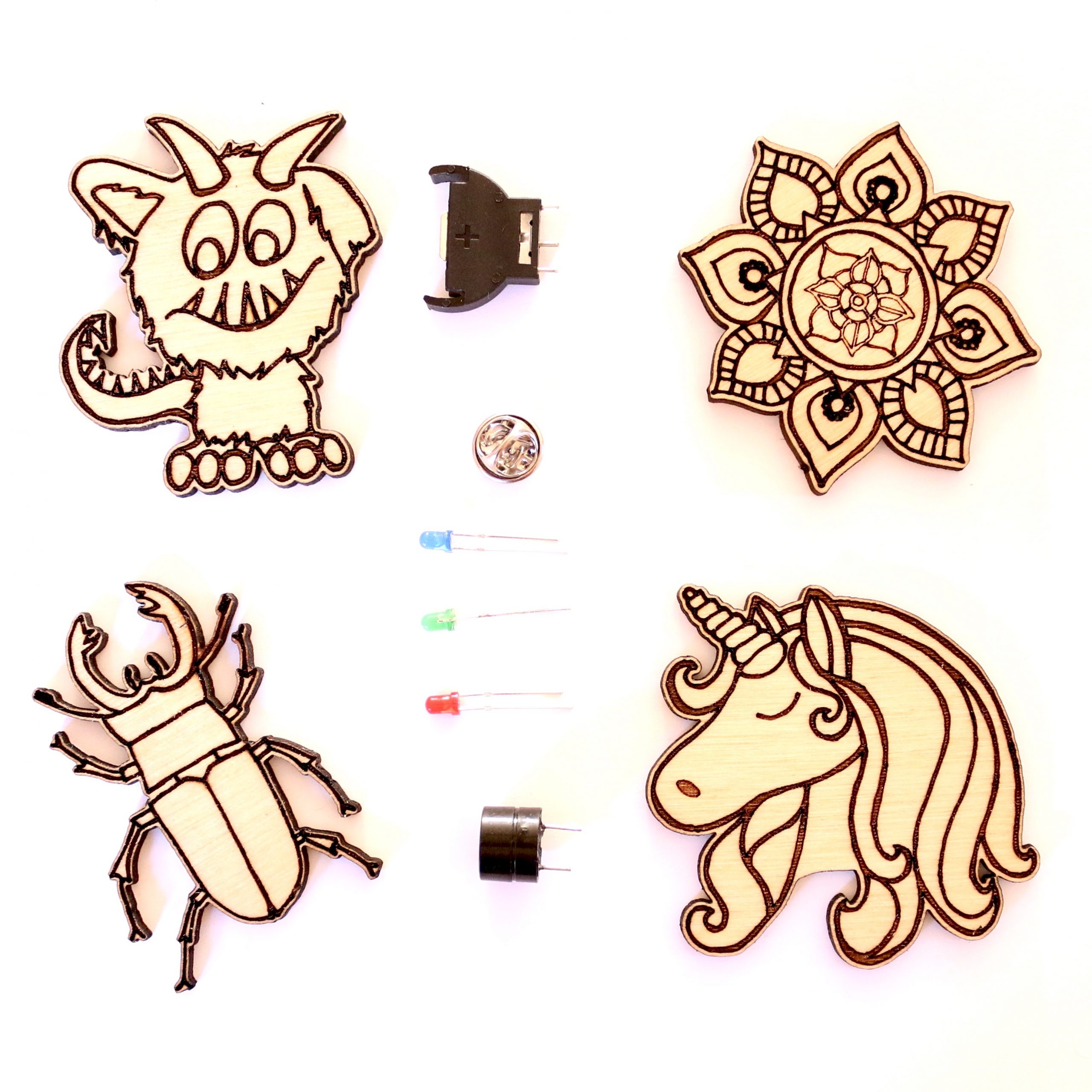
This box comes with four wooden buttons ready to be wired for light or sound. Subscriptions can be purchased in our shop.
Puppet

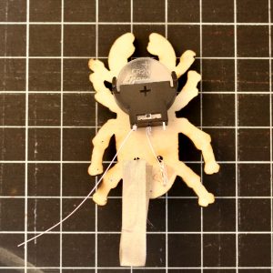
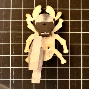
This is just a brief explanation of where to lay the positive and negative busses. Otherwise this puppet is constructed the same way as out robot from the starter pack.
Materials
- 1 wooden puppet
- 1 coin cell battery
- 1 popsicle stick
- copper tape
- glue gun
- 4 compatible 3mm LEDs
Instructions
Place your positive bus down the center and a negative bus down each side.
For a refresher on how to construct the rest of the puppet, see the tutorial for the robot that came with the starter pack.
Unicorn
We’ll use a nylon tape switch to light our unicorn button.
Materials
- 1 wooden button
- 1 coin cell battery
- 1 battery holder
- 1 button backing
- copper tape
- nylon tape
- glue gun
- 3 compatible 3mm LEDs (I used 2 blue and 1 white)
Instructions
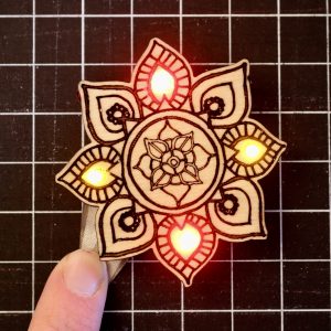
Mandala
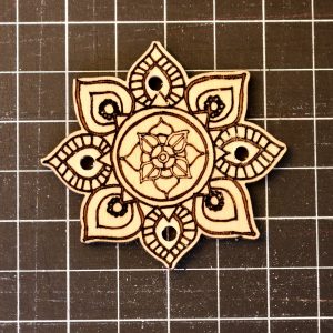
We’ll use a nylon tape switch to light our mandala button
Materials
- 1 wooden button
- 1 coin cell battery
- 1 batter holder
- 1 button backing
- copper tape
- nylon tape
- glue gun
- 4 compatible 3mm LEDs (I used 2 red and 2 yellow)
Instructions
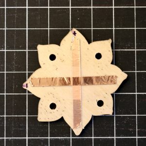
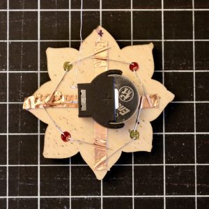
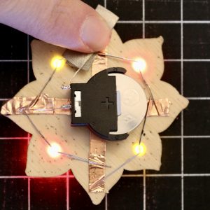
Flip the button over and add + and – labels. These are for your own reference.
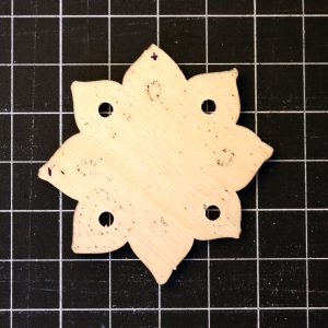
Lay some copper tape down on the positive axis. This will be our positive bus.
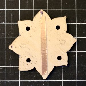
Add a small piece of clear tape to the center to insulate it from the negative bus we’ll be laying in the next step.
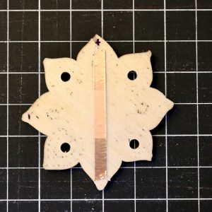
Lay another strip of copper tape down to be our negative bus.
Place two LEDs making sure their positive (longer) leads are on the positive bus and negative (shorter) leads on the negative bus.
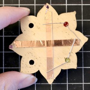
Use a small piece of copper tape to secure the negative leads to the negative bus. This would be a good time to do some testing.
Add the two remaining LEDs, again making sure the positives and negative line up.
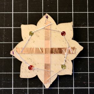
Secure the three remaining intersections with more copper tape.
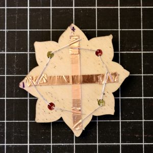
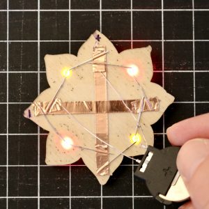
Test your work!
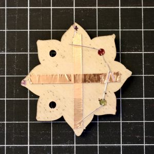
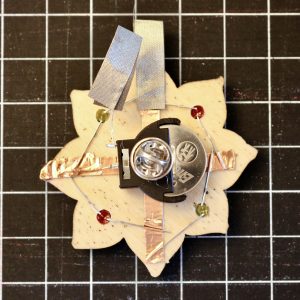
Use a hot glue gun to affix the battery holder to the center of the button so that the single negative lead (on the bottom middle) is aligned with the negative bus.
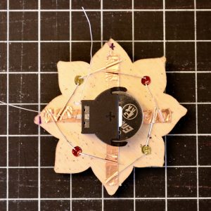
Trim the negative lead coming from the battery with your wire clippers. It shouldn’t reach past the edge of the button.
Tape negative battery holder lead down to the negative bus.
Trim the positive lead to about the same length or fold it over on itself and cut a 1.5″ – 2″ piece of nylon conductive tape.
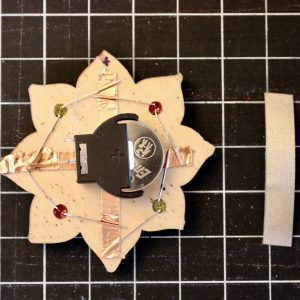
Place the tape under the positive lead. Bending the lead a bit (not pictured) will make it less likely to pull out in the next step.
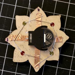
Fold the tape over onto itself. We are creating a tab for our fabric switch.
Test it by pressing it to the positive bus. You can stop here if you want.
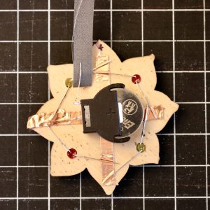
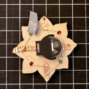
Fold a tab on another piece of nylon tape and attach it to the positive bus.

Test it out!
Turn it over and hot glue the button back onto the battery holder. Don’t get the battery!
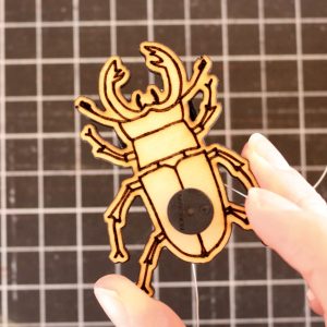
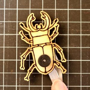
Stag Beetle
We’ll use a circuit driven buzzer to give our stag beetle sound.
Materials
- 1 wooden button
- 1 coin cell battery
- 1 batter holder
- 1 button backing
- copper tape
- nylon tape
- circuit driven buzzer
- glue gun
Instructions
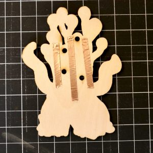
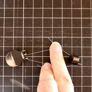
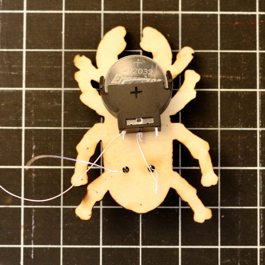
Test your battery and buzzer. The single middle lead on the battery holder is negative as is the shorter lead in the buzzer. (Pay attention to the lead, not the wire wrapped around it.)
Use a hot glue gun to glue your battery holder in place. You’ll want it as high on the button as it can go without being visible from the front.
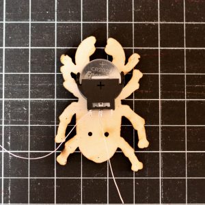
Place your buzzer on the front, threading your wire and leads through the holes. Your negative lead should go on the left when looking from the front.
Test to make sure your positive and negative are correctly oriented and then apply a bit of hot glue to the front to affix the buzzer in place.
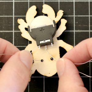
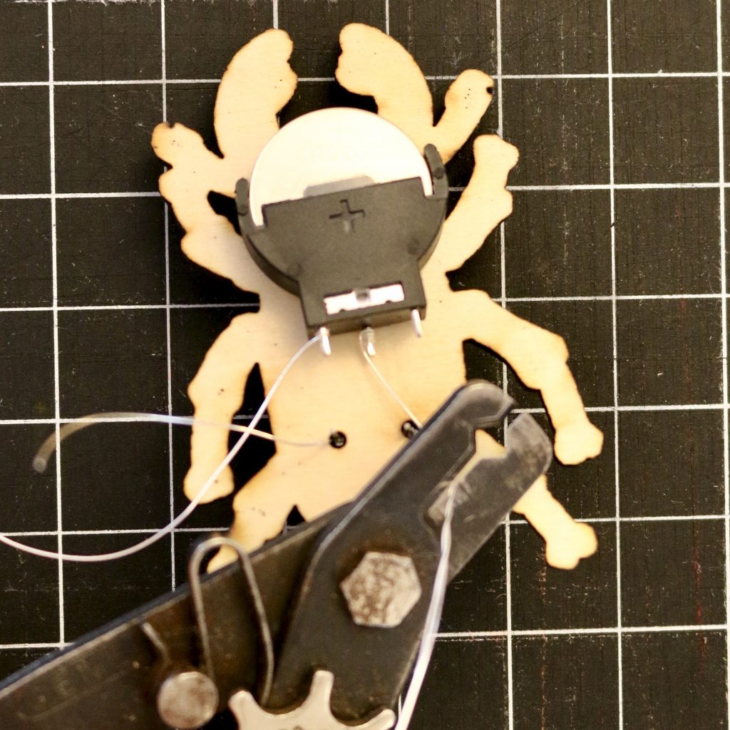
Twist the wires for the negative leads together.
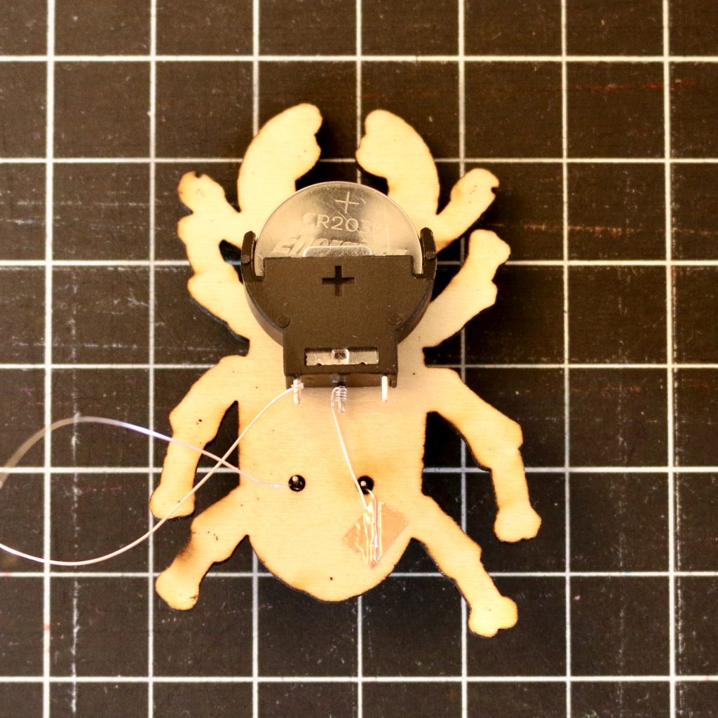
Clip the wires to be a bit shorter and secure the with a bit of copper tape. Make sure not to stray over to the positive side or we’ll have some accidental short circuits.
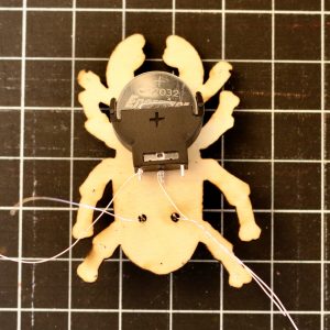
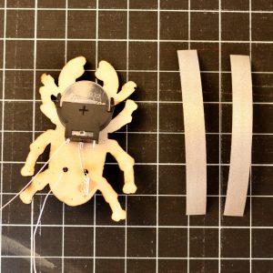
Cut two pieces of nylon tape about 3 inches long.
Fold the wire attached to the positive lead on the speaker in half leaving a bit of a loop. This will help keep it from slipping out from the tape in the next steps.

Peel half the backing off of a strip of nylon tape and place it under the wire.

Fold the tape in half onto itself, securing it onto the wire.
Repeat these steps for the wire attached to the positive battery lead. You have created your switch.
Make it “sing”!
To finish up, hot glue the pin back to the battery holder and put some dabs of glue on the leads coming up from the buzzer to keep them from poking or snagging things.
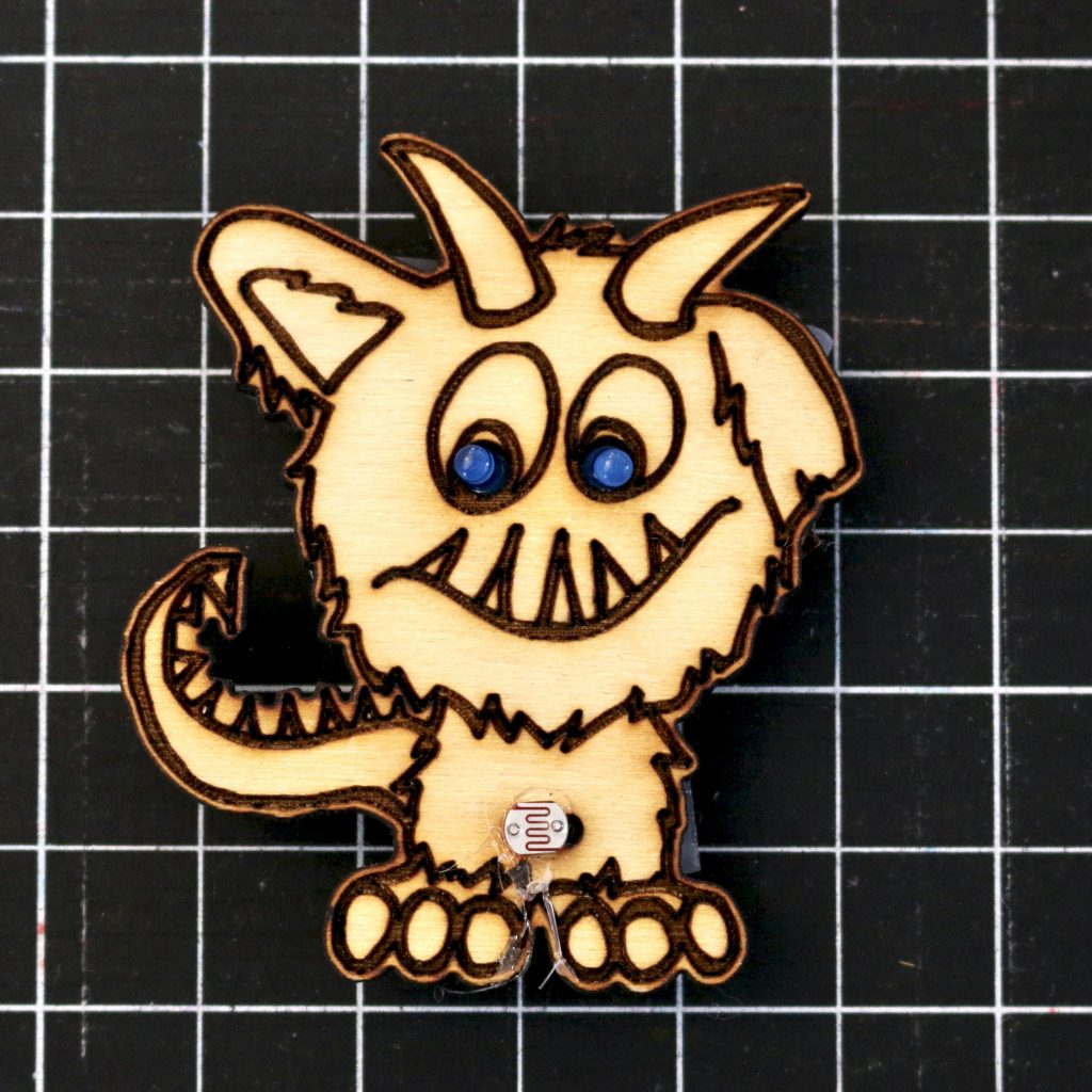
Monster
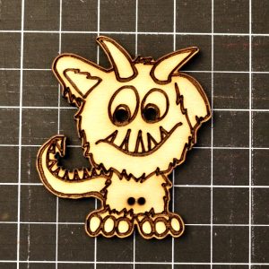
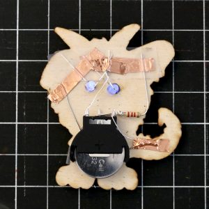
We’ll use a photo-resistor and voltage divider to make our creation glow at night.
Materials
- 1 wooden button
- 1 coin cell battery
- 1 batter holder
- 1 button backing
- copper tape
- 1 2.2k ohm resistor
- 1 photo resistor
- glue gun
- 2 blue 3mm LEDs
What are voltage dividers?
You can learn more about the math and mechanics behind voltage dividers at Sparkfun.
Instructions
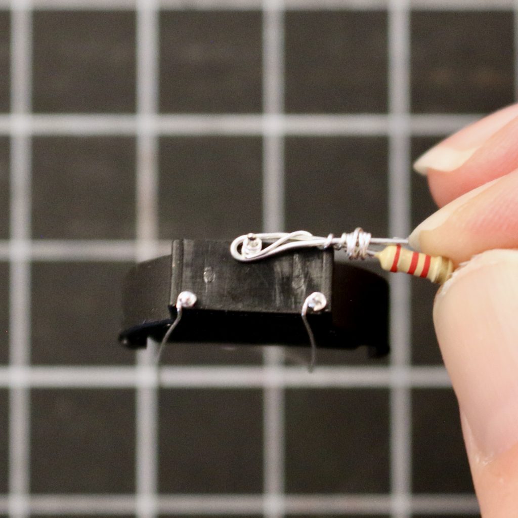
Find your battery holder and 2.2k ohm resistor. Bend one lead of the resistor in half.
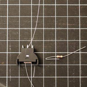
Place the resistor over the negative lead (center) on the battery holder and wrap the wire attached to the lead all around the folded over resistor lead.
Note: we could have just wrapped the wire around the resistor without folding it and placing it over the lead, but I found that it was prone to breaking that way. This is messier, but much more durable.

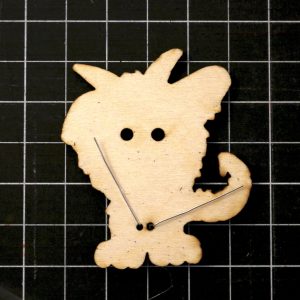
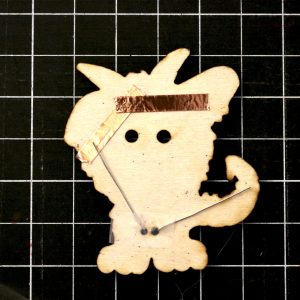
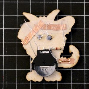
Set aside the battery holder and find your button and photo resistor.

Thread the photo resistor through its two holes and hot glue it in place.
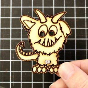
Bend the leads as shown.
Create the negative bus across the top. At the same time, place a very small bit of clear tape across the holes the photo-resistor goes through. This will keep the battery from touching the leads in the next step.
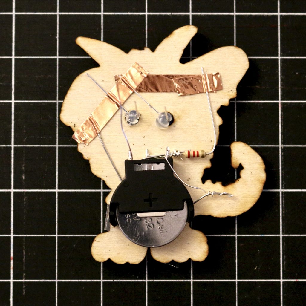
Hot glue the battery holder down.
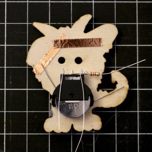
Bend the lead of the resistor up so that it connects to the negative bus.

Bend down the two negative leads on your blue LEDs.
NOTE: blue is intentional here. If you want to use a different color you would need a different resistor to get the correct range. This is touched on in the video.
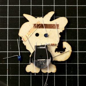
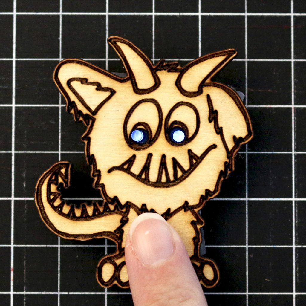
Place them as shown and use your thumb to hold them as you hot glue them in place. You’ll want to keep holding them until the glue sets. This probably requires some adult assistance.

Use two pieces of copper tape to secure all four leads (2 LED, 1 photo-resistor, 1 resistor) to the negative bus.

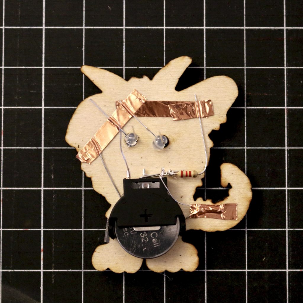
Wrap the positive lead battery holder that is closest to the tail around the photo-resistor lead that crosses the tail.
Use your wire clippers to trim the ends off so they fit on the tail and secure the down with a piece of copper tape.
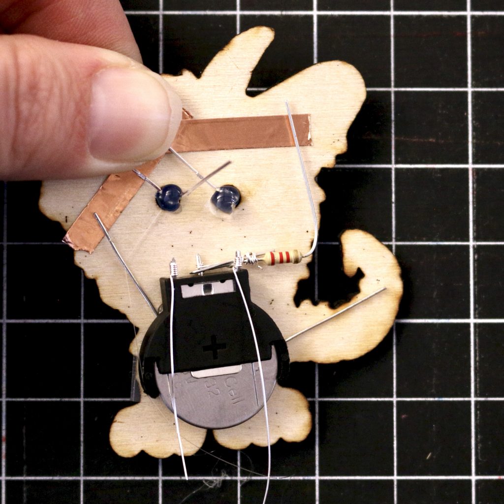
Place a piece of clear tape (made a bit more narrow along the length) over the negative bus to insulate it from the positive connection we’ll be making in the next few steps.
Wrap the two positive leads of the LEDs together. This just needs to be enough to secure them in place.
Wrap the remaining positive lead from the battery around the positive LED leads several times to create a good connection.
You should see your LEDs light up here. This is the first chance we’ve really gotten to test our circuit. If you flip the button over and expose the photo-resistor to light, the LEDs should turn off.
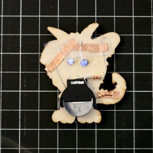
Fold the wires down careful not to touch and negative wires or the negative bus and secure them in place with some copper tape.
Glue your button back on, flip your creation over, and test it a few times!
NOTE: Because we are making use of a voltage divider, your button will continue slowly draining your battery even when the LEDs are off. My experience says that the batteries will still last about a month, but you should take them out if you put your button in storage.