This will be a living document that talks about the different components and techniques common to a lot of different projects.
Power
To make a circuit, one needs to create a loop through which electricity flows. Without the loop, there is no power. While it isn’t quite correct, it is standard practice to imagine electricity flowing out through the positive side and back in through the ground. A short circuit happens when the positive side loops back to the negative side without actually going through any of the components. We’ll address that more in-depth later.
We measure the amount of electricity available from the power source in volts and refer to it as voltage. Voltage can be regulated with a resistor.
Coin cell batteries
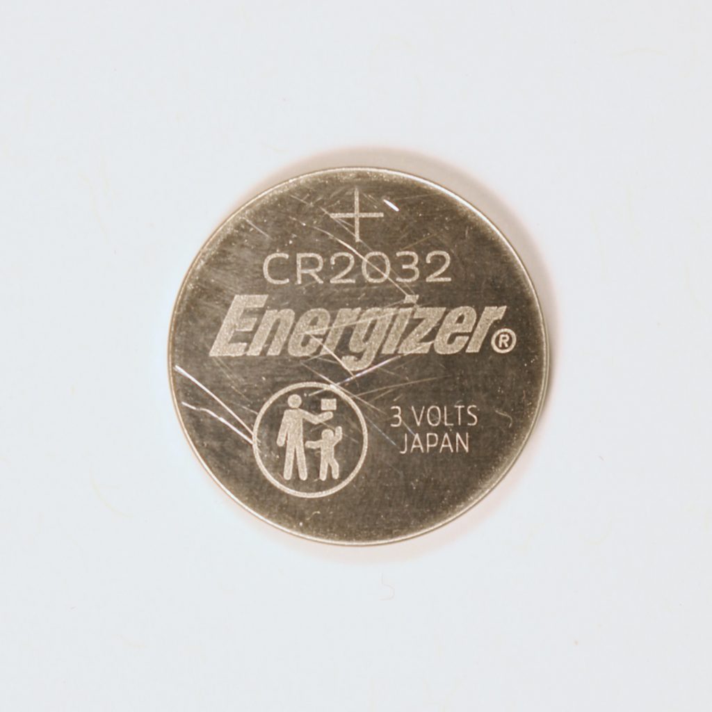
Coin cell – Positive Side 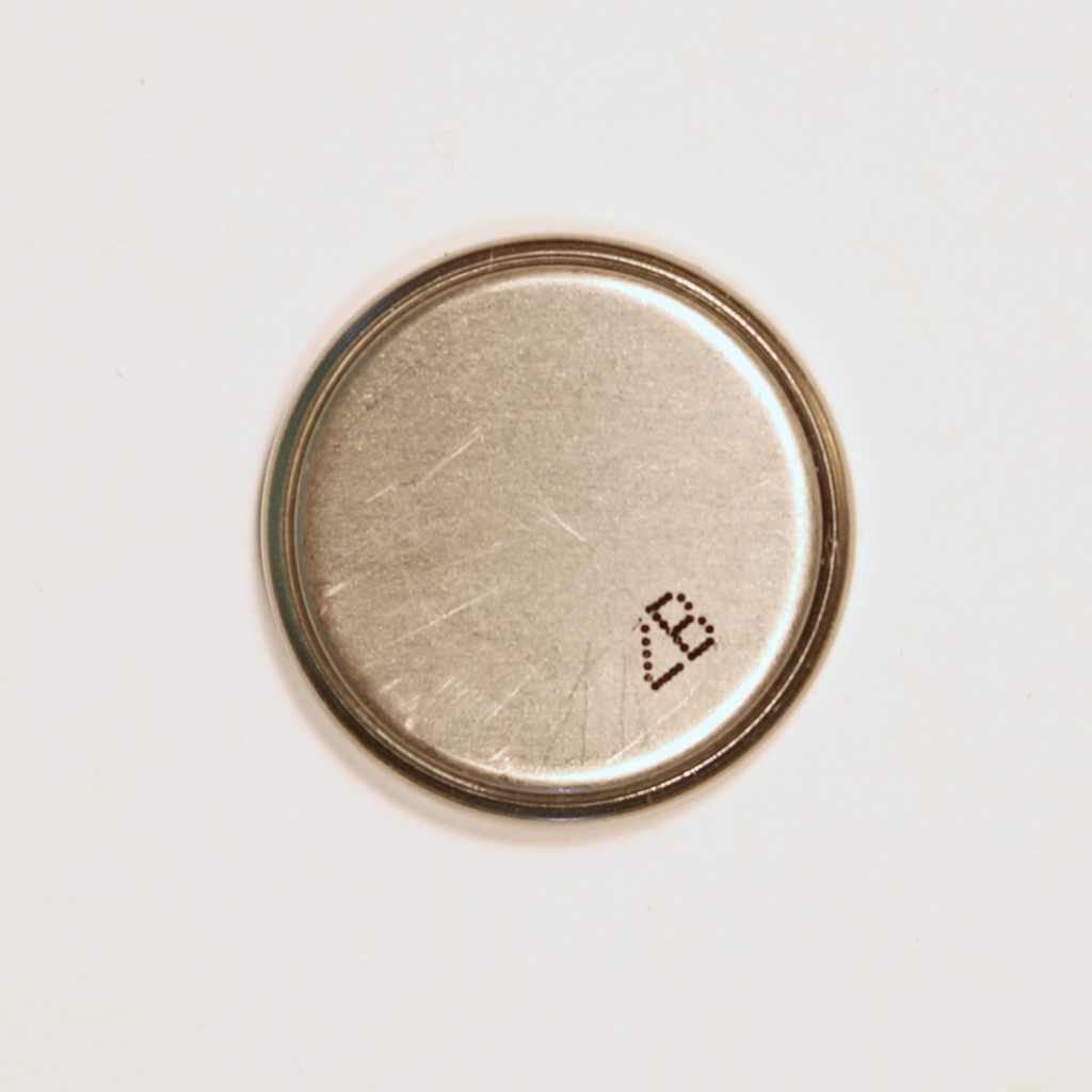
Coin Cell – Negative Side
Fully charged coin cell batteries are 3 volts and can be stacked to offer additional voltage. the positive casing of the battery wraps around the sides as well. You should be sure not to have any wire or tape coming from the ground brush up against it or you’ll get a short circuit.
Breadboard
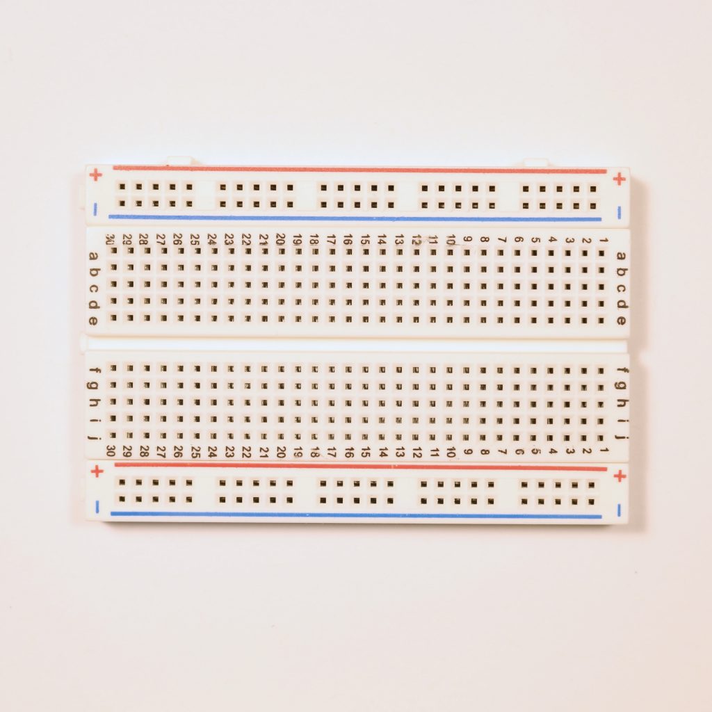
400-pin solderless breadboard 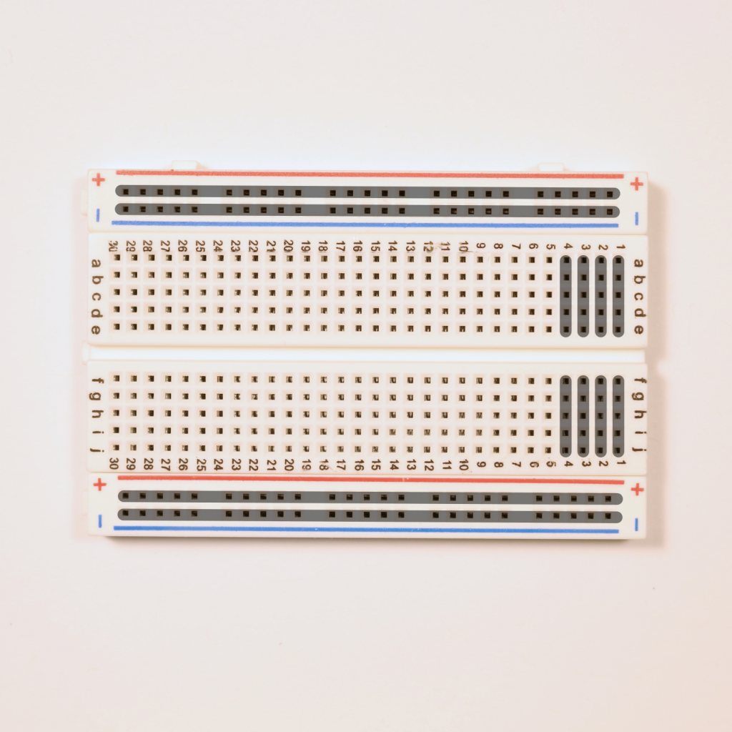
Breadboard with overlay
A bread board of this sort is used for prototyping creations and as an alternative to soldering components in place. Each hole is a place for an LED or resistor or lead from another component to plug in.
The two top and bottom rows are designated as power busses. We connect a battery’s positive and negative ends to the designated rows and then use the other holes to carry that power and ground over the the columns. Each 5-hole column is connected as well. The power busses and columns 1-4 show how they are connected in the overlay.
Connectors
Connectors isn’t a real category, but rather a convenient heading for a few different items.
Jumpers
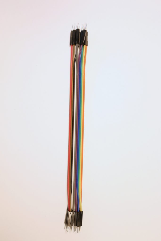
Male-Male Jumper Wires 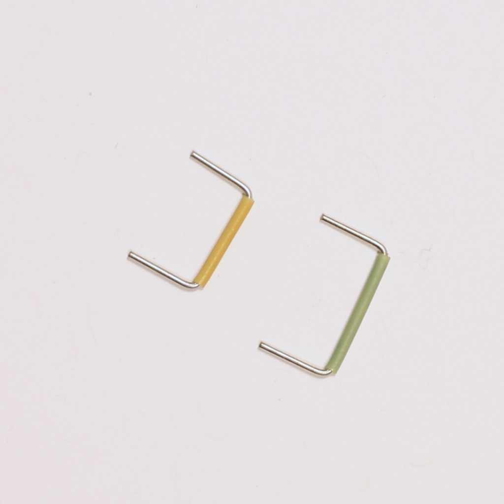
Pre-Formed Jumpers 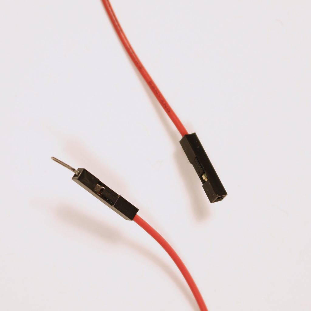
Male (left) and Female (right) Jumper ends
Jumper wires are used to move power to different places on the breadboard. Starter kits come with the jumpers on the left, but I’ll use the ones in the middle in the videos, because they’ll make everything a bit cleaner. Note how both types of jumpers don’t leave extra wire exposed risking a short circuit.
Alligator to Male Jumper
These clips have an alligator clip on one end and a male jumper on the other. They are useful for getting power to or from the breadboard.
LEDs
LEDs are light emitting diodes. They turn electricity into light. Different types of LEDs produce different colors, but the details of how they do that is beyond the scope of this tutorial.
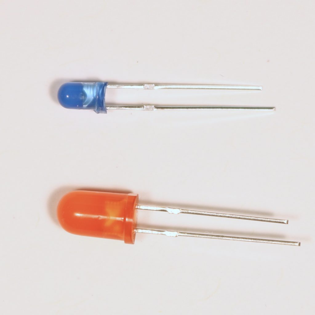
LEDs are polarized, this means that in order for LEDs to work, the current must flow through them in the correct direction. LEDs have a positive lead and a negative lead. The negative lead is shorter and generally the bulb (plastic part) has a flat spot in the base on the negative side.
Learn more about LEDs here: https://learn.sparkfun.com/tutorials/light-emitting-diodes-leds/all
Resistors
Resistors control the flow of electricity through the circuit. Less resistance means more electricity can flow through. More resistance means less electricity. Exactly how much electricity flows through depends on the voltage of the power source, so a resistor is more of a percent decrease rather than a fixed limit.
If too much power goes into a circuit it can blow out your components, so we use resistors to keep this from happening. Also, different components can use up too much of the power leaving nothing for other components. Resistors help keep that from happening.
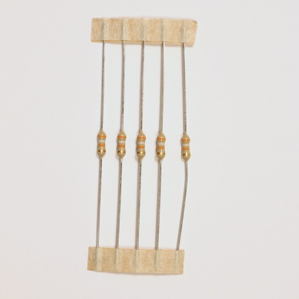
Resistors come held together by paper tape 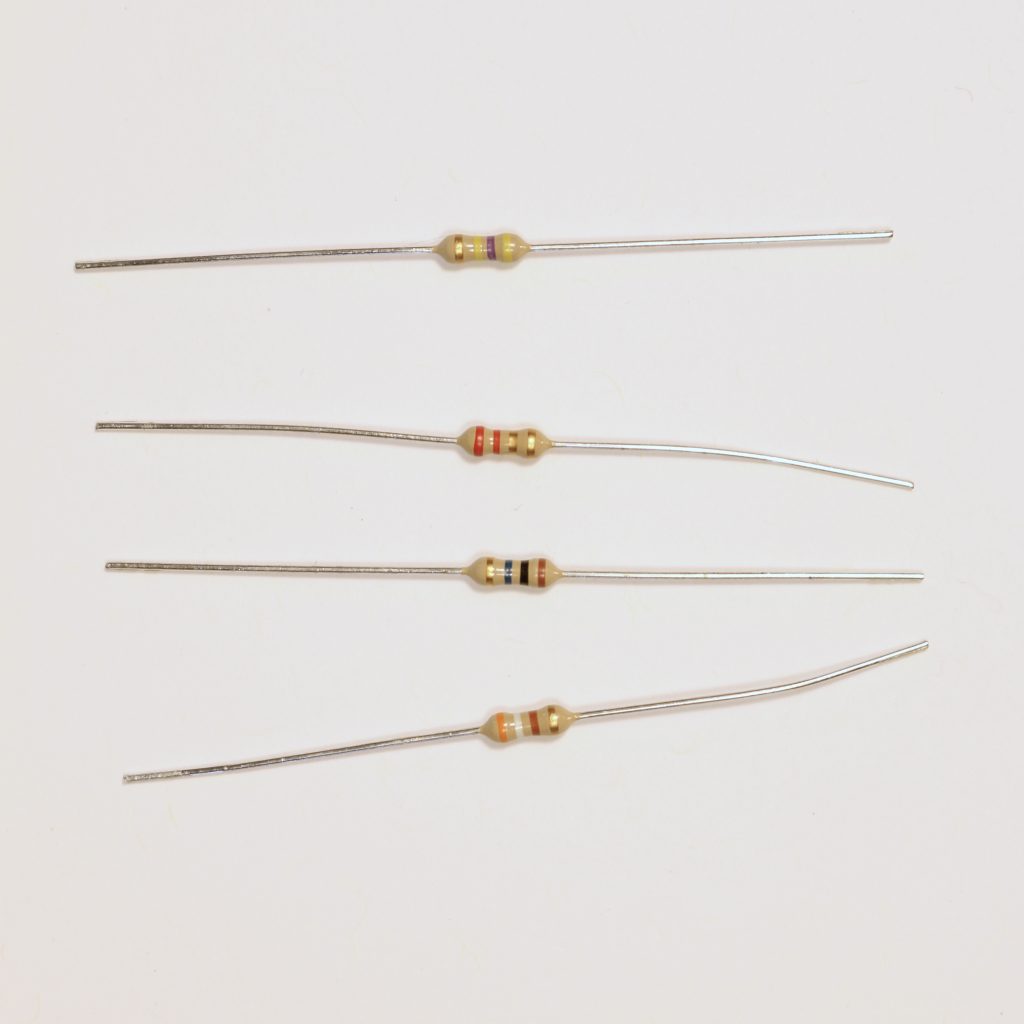
Four different resistors
Resistance is measured in ohms and resistors are labeled with colored bands. Most of the resistors you will come across have a gold band on one end. This is the tolerance, or the amount of error the resistor may have. The gold band represents a tolerance of ±5%. So a 220 ohm resister could actually be 209 ohms or 231 ohms. This won’t matter fo projects we’re working on, but could matter a lot for your computer or phone. Resistors are not polarized.
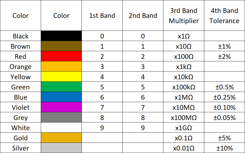
We read a resistor from left to right with the tolerance band (gold for us) on the right. In a four band resistor, the first two band are digits and the third is a multiplier. If you look at the top most resistor in our set of four above, it reads yellow, purple, yellow, gold. This translates to 47 times 10 k ohms (the greek letter omega Ω represents ohms, and k means 1000). So our resistor is 470 k ohms with a tolerance of 5%.
The second resistor is red, red, gold, gold, or 22 times 0.1 ohms or 2.2 ohms. Try on your own for the remaining two. You can also use a calculator to find resistor values. This is a good one: https://www.digikey.com/en/resources/conversion-calculators/conversion-calculator-resistor-color-code
Sparkfun has a much more in depth guide to resistors for those who are interested: https://learn.sparkfun.com/tutorials/resistors/all
Capacitors
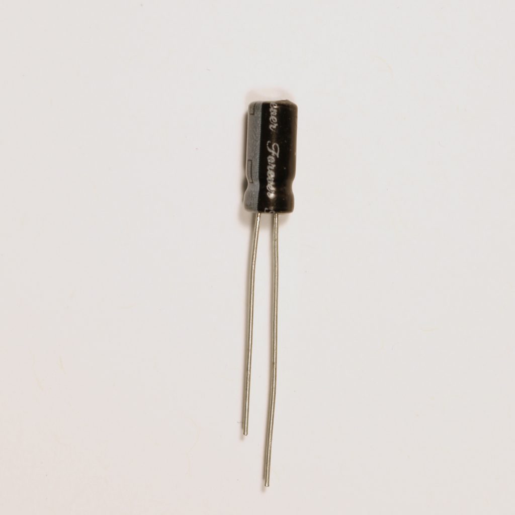
Capacitor 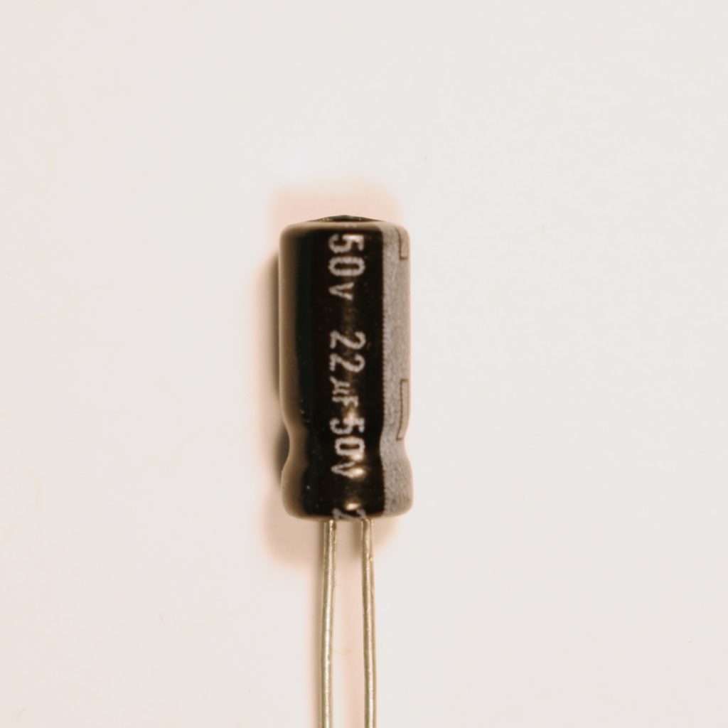
Capacitor close up
A capacitor is a charged storage device. This means that it can hold electricity to be discharged later. As electricity flows into it, it collects as much as it can hold. When electricity stops flowing into it, it releases its stored energy back into the system.
Capacitors are used to smooth over electrical “blips” to keep a system running for a short time if there is a break in the electricity. We can also take advantage of their properties in a more complex system to “steal” the electricity from the system in order to lower the voltage and flip a switch. We’ll use them in our 555 timers.
Pictured above is an electrolytic capacitor. Like LEDs they are polarized and have a positive (longer) and negative lead. The positive lead should connect to the positive power and the negative lead to the ground. On the close up the 50v indicated the voltage it can safely accept and the 22μF indicates that it can store 50 micro farads of electricity.
You can learn more about capacitors here: https://learn.sparkfun.com/tutorials/capacitors/all
Tools
Wire Cutter and Strippers
These have a sharp portion for cutting wire. Mostly we’ll use this for trimming resistors and cutting wire to length. The stripper part is used for removing the plastic coating from wire in order to expose a metal end.